
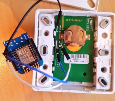
I recently did a proof of concept on shutters automation by hacking the remote
control: the idea is to wire the ESP in parallel with the remote control
buttons.
My remotes are Bubendorff 41677 but it should work with a lot of other remote
controls.
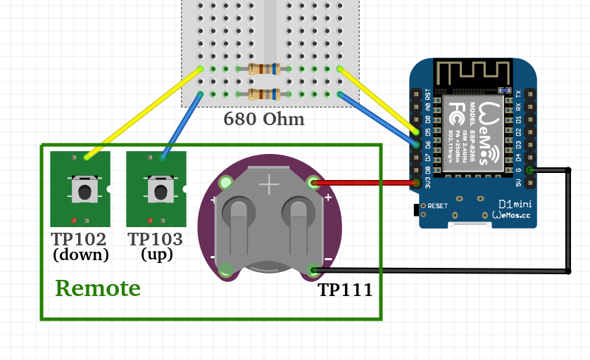
After poking with a multi-meter it appears that two test points are connected to the right signals:
- TP103: Up
- TP102: Down
The signal is active low: there is a pull-up resistor and it must be grounded to simulate the activation. A 680 Ohm resistor is used in series with each button of the remote to prevent current overshoot and maybe reduce power consumption, so I also used them:
You might not see the resistors on the top picture as I only had SMD 0603 on hand; look carefully :)
On the first attempt, I used the great ESPHome project to
simulate pressing the pushbuttons. I just created 3 virtual switches as a proof
of concept but for correct integration, a
cover component can be
used.
I split the configuration into two files: one generic and the other only
specifying the shutter name (room) and timings.
Per device file, called shutters-office.yaml in this example:
substitutions:
  # Used for HASS identifier
  name: office
  # Used for friendly name
  switch_name: "bureau"
  # Time from fully closed to fully opened
  full_time: "16s"
  # Time from fully closed to slightly opened
  partially_open_time: "5s"
  # Time for the "button pressed" event
  on_time: "150ms"

<<: !include shutters-common.yaml
Then the generic file called shutters-common.yaml:
esphome:
  name: shutters_${name}
  platform: ESP8266
  board: d1_mini

wifi:
  ssid: "MY SSID"
  password: "MY PASSWORD"

  # Enable fallback hotspot (captive portal) in case wifi connection fails
  ap:
    ssid: "Shutter fallback hotspot"
    password: "12345678ABCDEF"

captive_portal:

# Enable logging
logger:

# Enable Home Assistant API
api:

ota:

switch:
  # Define with GPIOs are used
  - platform: gpio
    id: up
    pin:
      number: 12
      inverted: yes
    restore_mode: ALWAYS_OFF
  - platform: gpio
    id: down
    pin:
      number: 14
      inverted: yes
    restore_mode: ALWAYS_OFF

  # Define template simulating the push on the button
  - platform: template
    name: Shutter ${switch_name} open
    turn_on_action:
      - switch.turn_on: up
      - delay: ${on_time}
      - switch.turn_off: up

  - platform: template
    name: Shutter ${switch_name} close
    turn_on_action:
      - switch.turn_on: down
      - delay: ${on_time}
      - switch.turn_off: down

  # Define template for slightly opening the shutter
  - platform: template
    name: Shutter ${switch_name} slightly open
    turn_on_action:
      - switch.turn_on: down
      - delay: ${on_time}
      - switch.turn_off: down
      - delay: ${full_time}
      - switch.turn_on: up
      - delay: ${on_time}
      - switch.turn_off: up
      - delay: ${partially_open_time}
      - switch.turn_on: up
      - delay: ${on_time}
      - switch.turn_off: up
As there is no feedback information on the shutter state the “slightly opened”
state is achieved by fully closing the shutter then opening it for a small
amount of time.
Once the ESP8266 or ESP32 is flashed the only thing remaining is to add it to
Home-Assistant, thanks to Configuration =>
Integrations => Set up a new integration => Search for ESPHome => enter
the ESP IP address. Et voilà, you are good to go and create powerful automations
in Home-Assistant.
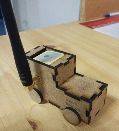
On the next version, I used a more clever strategy to command shutters from 0 to 100%, and a LoRaWAN board to allow battery-powered operation - to be published soon.
Share this post
Twitter
Google+
Facebook
Reddit
LinkedIn
StumbleUpon
Pinterest
Email