
I own a Rika Filo pellet stove, which I like, but it is on the expensive side of the market and the Wi-Fi module to remote control it was a no-go. This article describes the way I reverse-engineered the radio protocol.
As it is my sole heating system and winter is coming, I wanted a non invasive approach to avoid breaking anything, so I hooked up a logic analyzer to record the commands sent by the micro-controller to the radio chip, which helped me to learn the RF parameters + actual payload.
1. Hardware
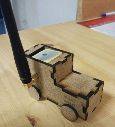
The wireless temperature sensor is really simple:
- Battery holder - with polarity inversion protection :-)
- ATmega48 micro-controller
- TI CC1101 radio transceiver
- Temperature sensor in a SOT-23 package?
Fortunately, the ATmega is using a programming port called “ISP”, which shares the SPI port, and there is a nice 0.1" 2x3 header footprint on the PCB. I soldered the pin headers and easily used them to connect a logic analyzer, in order to spy the commands sent by the ATmega. The only missing signal was the chip select, which I found on a pull-up resistor between the batteries.
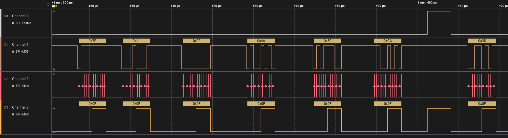
2. Understanding the SPI commands
I initially used LogicAnalyzer by El Dr. Gusman: a nice project based on Raspberry Pi Pico RP2040, which I recommend. Then I lent it to a friend so I finished with my work’s Saleae device.
As Dr. Gusman’s logic analyzer can export to Sigrok I wanted to use the integrated CC1101 decoder to figure out the commands sent by the device. It did not work, I tried to debug it, figured out that the bug was already fixed, compiled the latest Sigrok then… the decoder was not able to decode my frames for a reason I did not understood. I gave up and wrote a quick and dirty parser which, in the end, would have been a faster solution :).
3. Radio parameters
Decoding the SPI commands gave the following parameters:
- Modulation: FSK
- Manchester encoding: No
- Forward Error Correction (FEC): No
- Carrier frequency: 868.317 MHz
- Frequency deviation: 19042 Hz
- IF frequency: 304.687 kHz
- Bandwidth: 203.125 kHz
- Datarate: 115051 bauds
- Sync mode: 30/32 bits
- Preamble length: 32 bits
- Sync word: 0x4904
- Whitening: Yes (Seed: 0x01FF)
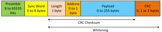
- FSK header: implicit/fixed length, ie address and size are not added by the chip
- CRC: Yes (16 bits. polynomial: XX, init: XXX)
- Transmitted packet length: 5 bytes
- Bit shift between preamble and sync word (not in SPI recording, I discovered it later…)
Despite the Sigrok CC1101 protocol analyzer issue, it was not that hard. I had everything I needed to simulate the Rika temperature sensor, so I took a Semtech LR1110 eval board I had laying on my desk, set the right parameters and the payload, flashed the eval board and… it did not work :(
4. Radio analysis
I doubled check each parameter, they where correct. What could be the issue then? Time to look at the FSK signal itself: I used an SDR stick with the wonderful Universal Radio Hacker software to record the transmitted payload and try to understand the issue.
4.1 Preamble
Small detail, the preamble was shifted by one because the TI chip is transmitting 0xAA, but the Semtech chip is transmitting 0x55. Fortunately, the LR1110 allows to select the number of bits of sync word to transmit, so I can added the missing ‘0’ bit before my sync word and set its length to 33 instead of 32.
4.2 What the…Whitening?
Now the difficult part: the preamble and the sync word are the same between both records, but not the payload and the CRC. It has to be a whitening issue! Both chips are using a PN9 algorithm, and I set in the Semtech chip the same init than TI is using: 0x01FF. What next? It took me a while to understand that the CC1101 starts the whitening on the most significant bit of each byte, while LR1110 starts the whitening on the least significant bit!
Whitening: Also called scrambling, is to avoid long series of the same bit. Alternate bits helps the receiver to avoid desynchronization as TX and RX clock do not perfectly match.
4.3 Wrapping-up
Knowing this I was able to implement the whitening in software, and this time, it worked! The pellet stove was receiving my packets :-)
Note: I also had to implement the CRC16 as the whitening is applied to it:
5 Payload analysis
5.1 Header
The payload is surprising, in FSK we explicit header can often see preamble | syncword | payload length | address | payload |. In our case, the DIP switch on the board allows to change the second byte, which corresponds to the address but the first byte is always 0x11, so it might actually be a custom Rika header…
=> header is one byte, 0x11
5.2 Address
The second byte is an address directly correlated to the first three DIP switches, 1 is the LSB, and 3 is the MSB:
| Switch #3 | Switch #2 | Switch #1 | Address value |
+ --------- + --------- + --------- + ------------- +
|    Off    |    Off    |    Off    |      0x00     |
|    ...    |    ...    |    ...    |       ...     |
|    On     |    On     |    Off    |      0x06     |
|    On     |    On     |    On     |      0x07     |
Note on switch #4: as written in the documentation it is selecting power output of 1 dBm (Off) or 10 dBm (On).
5.3 Battery
The last byte was more difficult to figure out and I must admit that I decided to not bother with it until I found Hublol’s github project when writing this article, who already did some reverse engineering. Even if the radio parameters are not fully described on Github he found that this byte was the battery. I do not plan to use it, but for the completeness of the reverse engineering I hooked my lab power supply and recorded the value transmitted when I swiped the voltage from 1.8 V to 3 V:
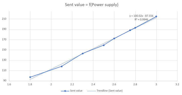
| Supply voltage (V) | Value sent | Trendline |
+ ------------------ + ---------- + --------- +
|         3.0        |     215    |    213    |
|         2.8        |     193    |    193    |
|         2.6        |     172    |    172    |
|         2.5        |     159    |    162    |
|         2.3        |     143    |    142    |
|         2.1        |     118    |    122    |
|         1.8        |      97    |     62    |
=> The function encoded_value = voltage_V * 100.02 - 87.556
5.4 Temperature
I eventually figured out that the temperature is encoded in the first two bytes, it is weird as I was not able to find a “usual” way to encode the temperature… I then swiped the values with steps of 256 and read the temperature displayed by the stove: the conversion is not linear!
As we usually heat around 19°C, I did a linear trendline between 15 and 22°C where I want the highest precision: the room never reached more than 22°C thanks to the stove, and the temperature accuracy below 15°C is not important as the stove need to heat at full power
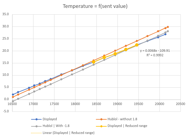
| Value | Displayed        |           Hublol         |         Trendline        |
|  Hex  | temperature (°C) | temperature (°C) | delta | temperature (°C) | delta |
+ ----- + ---------------- + ---------------- + ----- + ---------------- + ----- +
| 4080  |       2.0        |        -0.80     |  2.8  |         2.4      | -0.4  |
| 4500  |      10.2        |         8.20     |  2.0  |        10.2      |    0  |
| 4600  |      11.9        |        10.20     |  1.7  |        11.9      |    0  |
| 4700  |      13.7        |        12.20     |  1.5  |        13.7      |    0  |
| 4800  |      15.4        |        14.20     |  1.2  |        15.4      | -0.1  |
| 4900  |      17.2        |        16.20     |  1.0  |        17.2      |    0  |
| 4A00  |      18.8        |        18.20     |  0.6  |        18.9      | -0.1  |
| 4B00  |      20.5        |        20.20     |  0.3  |        20.7      | -0.1  |
| 4C00  |      22.4        |        22.20     |  0.2  |        22.4      |    0  |
| 4D00  |      24.0        |        24.20     | -0.2  |        24.1      | -0.1  |
| 4E00  |      25.6        |        26.20     | -0.6  |        25.9      | -0.3  |
| 4EAD  |      26.8        |        27.55     | -0.8  |        27.0      | -0.2  |
=> The function is encoded_value = temperature_celsius * 0.0068 - 109.91.
6. Code
The library to create the payload, as well as the whitening and CRC, is on available on Gitlab.
7. Conclusion
I am now able to replace Rika’s temperature sensor, so I will be able to create a “smart thermostat” and remotely control my stove to rise the temperature when I am returning from vacation, or prevent its start when the sun will heat the house in the next hour or so. Next step is to create a dedicated board to be able to control the remote from LoRaWAN.
I tested it against Rika pellet stove Filo and Sumo, but I am surprised that the temperature encoding differs so much from Hublol’s findings; he might have a more recent stove where they changed the electronics, I will ask him…
Share this post
Twitter
Google+
Facebook
Reddit
LinkedIn
StumbleUpon
Pinterest
Email