
After the STM32L151, I am now designing a board for STM32L052. Following are some notes about ST application notes I read to design an board.
All documents can be found
here.
Datasheet,
Reference manual,
Errata sheet.
Hardware development
AN4467 - Getting started with STM32L0xx hardware development
Hardware
- Voltage range, p6
- Full speed (Range 1) : 2.0 to 3.6 VDC
- USB : 3.0 to 3.6 VDC
- Power supply capacitors, p11
- 100 nF by VDD pin
- Min 4.7µf for the chip, 10µF recommended
- 100 nF by VDDA pin
- 1 µF for the chip, or 10 µF if high sampling rate ADC
- Reset circuit, p16
- No component mandatory
- 10 nF to 100 nF pull-down can be added as EMS protection
- Clock, p17
- No external required
- Better to provide a 32.768 kHz quartz for RTC accuracy
- Recommended load capacitance for HSE is 2 to 7pF
- SWD port, p25
- Signals required are: NRST, SWDIO, SWCLK, GND
Debug
- No JTAG port
- SWD: SerialWire Debug
Boot
- See AN2606
- Boot configuration
BOOT1bit inuser option byte, set to 0 by defaultBOOT0pin, inline 10 kOhm resistor recommended
- Boot selection (
BOOT1-BOOT0)x-0: Flash memory0-1: System memory (ST bootloader)1-1: SRAM memory
- ST bootloader on
USART1,USART2(pulls-up required onTXandRX)SPI1,SPI2(pull-down required onCLK)
- No DFU
- All pins are in floating input state during reset => Do not forget a weak pull for components like MOSFET…
Oscillator design guide
AN2867 - Oscillator design guide
- §4.2, p23 - Detailed steps to select an STM32-compatible crystal
- §5, p26 - Some recommended resonators for STM32 microcontrollers
- §7.1, p30 - PCB design guidelines
Touch sensing
- AN3960 - ESD considerations
- Most used method is to add an inline 50 Ohm
- AN4312 - Guidelines for designing touch sensing applications
- If a LED is placed closed to touch interface, use 10 nF bypass capacitor (p15)
- If possible use FT I/O instead of TT as they are clamped to VDD, or use Shottky diode with capacitance <5 pf (p15)
- Recommended to use the same shape for all electrodes (p18)
- Recommended electrode size is 4 times panel thickness
USB
AN4879 - USB hardware and PCB guidelines
- Signal lines
- 90 ohm +/-15% differential
- ESD protection circuits like ST USBLC6 are highly recommended
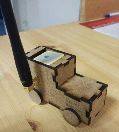
Let’s put it into practice
An open-source dev. board I designed can be found here.
Share this post
Twitter
Google+
Facebook
Reddit
LinkedIn
StumbleUpon
Pinterest
Email