
As a part of my future home automation called
NoteRF, I need some devices other than a
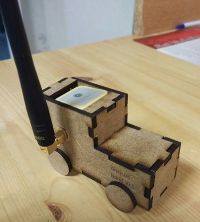
Raspberry Pi grabbing weather and pollution data from the internet: I designed a
PCB and throw some lines of code on it.
Currently, the devices are only sensors, but I plan to implement some actuators
later. Everything communicates wirelessly with the help of
HopeRF RFM69hw, I will write
something on the PCB and publish them as soon as I have the time to do some
minor corrections to the Eagle files.
As it might help some other people, it is available on Github. I tried to keep things simple (who said stupid ? :p ), and easily configurable, but engineers always like complicated ways and it might not appear easy to everybody, just let me know!
1. Communication protocol between sensors and the gateway
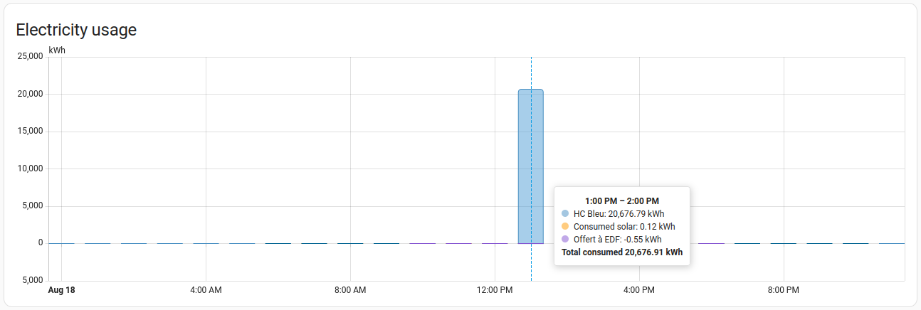
Every sensed data is written in a structure, so the code adds an ID and sends the structure as is. The ID will help the gateway to copy it in the right structure then forward the values on the serial link. I tried to minimize transmitted bytes over the air, which implies, when possible, to use an integer instead of float; then the final receiver (after gateway’s serial link) will divide it. For example, a transmitted temperature will be 1640/100=16.40, 2 bytes saved!
2. Communication between the gateway and… something!
On the gateway’s serial side, there are two cases:
- The node send some text, it will be outputted by
[NodeID] Text\nThe node send data, it will beNodeID|DataType|Data_1|Data_2|...|Data_N|BatteryLevel|RSSI\n
Each communication is terminated by \n
3. Configuration
I split the code into two files: the main source dedicated to the sensor or the
gateway and the file configuration.h to allow easy configuration without
having to mess with the code.
  /*************          RF configuration      *************/
  #define RFM_NODEID        1      // Unique for each node on same network
  #define RFM_NETWORKID     110    // The same on all nodes that talk to each other
  #define RFM_GATEWAYID     0      // Gateway to reach
  #define RFM_FREQUENCY     RF69_433MHZ
  #define RFM_ENCRYPTKEY    "sampleEncryptKey" // Exactly the same 16 characters/bytes on all nodes!
  #define RFM_IS_RFM69HW           // Uncomment only for RFM69HW! Leave out if you have RFM69W!
  #define RFM_ACK_TIME      30     // max # of ms to wait for an ack
  #define RFM_POWER_LEVEL   10     // Set power level - TBC for RFM96HW

  /*************          Node configuration      *************/
  // #define BATTERY_VCC      // Sense Arduino's VCC battery with 1.1V internal ref
  #define BATTERY_VIN         // Sense battery with divider on A7

  // Data types  -  Uncomment DATA_XXX to activate it
  #define DATA_DHT22      1
  #define PIN_DHT22_DATA  4
  #define PIN_DHT22_POWER 5

  #define DATA_TELEINFOCLIENT 2
  #define PIN_TELEINFOCLIENT 3

  #define DATA_DS18B20   3
  #define PIN_DS18B20    6

  // Others
  #define DEBUG_ON              // Uncomment to activate debug
  #define SERIAL_BAUD   115200  // Set serial communication speed
Configure node ID, the network, the gateway ID, frequency of the module, and encryption key… Everything you need to know is in the comments.
Just set RF parameters, comment DATA_XXX of non-connected sensors, and, voilà!
Don’t forget to comment DEBUG_ON if you want to save battery life, but
uncomment it if you need some debug data.
4. Power source
For the recall, the RFM69 power supply range is [1.8V; 3.6V]. In most cases, three power sources are used:
- Direct powering from wall plug with regulated 3.3V
- No need to monitor the battery.
- Direct powering through 2xAA or 2xAAA batteries
- We use the internal 1.1V reference to monitor the battery level. It might need
some calibration at your operational temperature. Use
#define BATTERY_VCC - Powering through the voltage regulator (18650 Cell, 2 cells lipo…)
- Use a voltage divider, uncomment
#define BATTERY_VINand set the appropriate multiplying factor.
Share this post
Twitter
Google+
Facebook
Reddit
LinkedIn
StumbleUpon
Pinterest
Email