
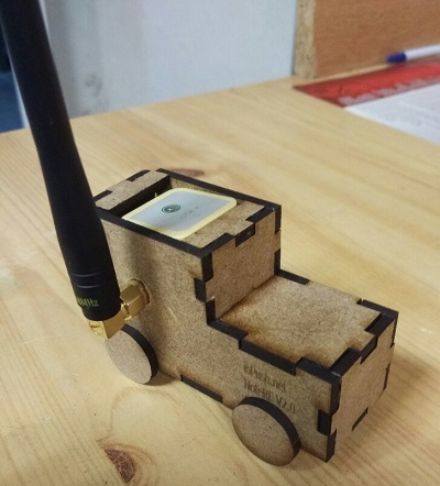
Kongduino kindly sent me a WisDuo RAK3272s few weeks ago, it is a a breakout board for RAK nice module (RAK3172) around the STM32WL5 system on chip from ST. Let’s see how to use STM32 CubeMX to generate the initialization files and the LoRaWAN stack, then setup Visual Studio code debugger.
1. STM32 CubeMX
Download STM32 CubeMX from ST website,
install it as instructed.
Open it then create a new project thanks to ACCESS TO MCU SELECTOR. In the Part Number searchbox look for STM32WLE5CC then select STM32WLE5CCUx and Start Project. CubeMX will now create empty project with only the RF and oscillator pins initialized plus some core peripherals, we have to select the features we want:
1.1 Pinout & configuration tab
Analog -> ADC
Check Vrefint Channel, it will be used by the demo application.
Timers -> RTC
Check Activate Clock Source and Activate calendar. Add the following values in configuration section, tab User constants:
RTC_PREDIV_A:((1<<(15-RTC_N_PREDIV_S))-1)RTC_N_PREDIV_S:10RTC_PREDIV_S:((1<<RTC_N_PREDIV_S)-1)
In Parameters Settings tab:
Bin mode:Free running binary modeAsynchronous predivider value:RTC_PREDIV_A
Connectivity -> SUBGHZ
Check Activated to use the LoRa IP.
Connectivity -> USART2
To send traces (printf) from the STM32 to the computer.
- Select
ModetoAsynchronous - In
Configurationsection, tabDMA Settings:- Click on
Add - In
DMA requestselectUSART2 TX - In
ChannelselectDMA 1 channel 5 - In
DirectionselectMemory to peripheral - In
PriorityselectLow
- Click on
- Tab
GPIO Settingsshould already have:PA2asUSART2_TXPA3asUSART2_RX
Middleware -> LoRaWAN
Check enabled to add the LoRaWAN stack to the project then in the configuration section, tab LoRaWAN Middleware:
lorawan_conf: select your regionTx Rfo Config:CONF RFO HP
In tab LoraWAN Application:
Application:End Node skeletonLoRa App->Active region: Select your region
In tab Platform Settings:
| Name | IPs or Components | Found Solutions |
|---|---|---|
| ADC | ADC: Vrefint channel | ADC |
| USART | USART: Asynchronous | USART2 |
| RTC | RTC: RTC Enabled | RTC |
Note: If you do not know which EUI/Key to use follow the chapter TTN OTAA Device Registration in RAK’s quickstart.
In tab LoRaWAN commissioning:
- Check
Static Device Eui - Fill
LoRaWAN device eui,App/JoinEUIandApplication key
System core -> NVIC
Check SUBGHZ Radio Interrupt.
Pin configuration
On the STM32 picture click on:
- Pin
PB0: selectVDDTCXO - Pin
PC14: selectRCC_OSC32_IN - Pin
PC15: selectRCC_OSC32_OUT
1.2 Clock Configuration tab
- In
RTC Clock MuxselectLSEinput MSI RCcan be pushed to48000
1.3 Project Manager tab
Set Project name, then in Toolchain/IDE select Makefile.
The project is ready, click on GENERATE CODE in top right corner.
When generated you can open the folder in your favorite editor, I will use VS Code.
2. Configure the C code
Now the program skeleton is generated but it can not be compiled yet, otherwise the compiler with output warnings like:
#warning user to provide its board definitions pins
We have to provide some specifics about the radio pins. Download radio_board_if_c.patch and radio_board_if_h.patch, place them in the root directory of your project then:
patch -u LoRaWAN/Target/radio_board_if.c -i radio_board_if_c.patch
patch -u LoRaWAN/Target/radio_board_if.h -i radio_board_if_h.patch
3. Compile the binary
Download arm-none-eabi toolchain, add it to your path then it is as simple as make -j.
4. Flash the microcontroller
RAK official documentation is using a serial<>USB converter and the integrated STM32 serial bootloader to flash the firmware, but I prefer an ST-Link as I will also be able to debug the code.
4.1 ST-Link pinout and wiring
You can use an ST-Link or any Nucleo header as long as it is broke from the target board or the jumpers ST-LINK are removed. Then the connector SWD/CN4 must be wired to the RAK module, Nucleo’s serial<>USB converter can be used thanks to CN3:
| Signal name | Nucleo header | RAK3272s |
|---|---|---|
| VDD_ref (optional) | CN4->1 | 3V3 |
| SWCLK | CN4->2 | SWCLK-PA14 |
| GND | CN4->3 | GND |
| SWDIO | CN4->4 | SWDIO-PA13 |
| nRST | CN4->5 | RST |
| UART_TX | CN3->1 | UART2_TX |
| UART_RX | CN3->2 | UART2_RX |
| Power Supply (3.3V) | CN1->1 | 3V3 |
4.2 Use ST-Link USB mass storage
You can flash the microcontroler by copy/pasting the .bin file in the ST Link folder.
4.3 OpenOCD
Required only if you want to use the debugger. As of december 2021 most OpenOCD releases does not yet include STM32WL support, it has to be compiled from the sources. The steps are easy for Linux:
git clone https://git.code.sf.net/p/openocd/code openocd-codeapt install make libtool pkg-config autoconf automake texinfo libusb-1.0-0 libusb-1.0-0-dev./bootstrap./configure --enable-stlinkmakemake install
4.5 VS Code
Install the extension Cortex-Debug if you want to use the debugger, then edit the launch.json file, or create it if required, to have
{
    "version": "0.2.0",
    "configurations": [
        {
            "name": "Cortex Debug",
            "cwd": "${workspaceRoot}",
            "executable": "./build/${workspaceFolderBasename}.elf",
            "request": "launch",
            "type": "cortex-debug",
            "servertype": "openocd",
            "configFiles": [
                "interface/stlink.cfg",
                "target/stm32wlx.cfg"
            ],
        }
    ]
}
5. LoRaWAN uplinks
Register your device in a network server like The Things Network, then you should see the JoinRequest/JoinAccept!
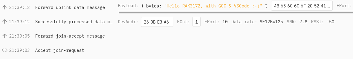
If you have any issue the project is available on Gitlab. The project also contains a populated SendTxData() function to actually send uplinks :)
6. Next steps
Now that we are connected to the network the next post should be about optimizing power consumption and enter in stop mode to only consume µAmps when not sending data.
Share this post
Twitter
Google+
Facebook
Reddit
LinkedIn
StumbleUpon
Pinterest
Email